FITTING GEOMETRY
- Segmented Bends
PE Segmented bends, are manufactured by butt fusion welding PE pipe segments together to specified geometric angles ie 90°, 45°, 30°, and shall comply with the dimensional requirements of ISO 4427-3 Section B.3. For a full set of fitting dimensions refer to the fitting manufacturer.
For Segmented bends fabricated out of pipe segments cut from pipe complying with AS/NZS4130, the following de-rating calculation of the PN shall apply:
PN = fB × PN Pipe
Where
f B =The derating factor applied to the bend segment (Refer to Table 1)
PN = The nominal pressure of the pipe.
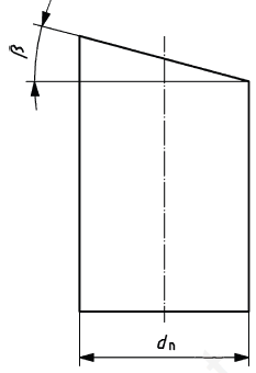
Figure 1. Segment Design
Figure 1. Segment Design
dn nominal outside diameter
β cut angle
The cut angle β, Figure 1, shall not be greater than 15°.
Table 1: De-rating Factors for Segmented Bends
| Cut Angle β | De-rating Factor fB |
| ≤ 7.5° | 1.0 |
| 7.5 < β ≤ 15° | 0.8 * |
|
*In accordance to ISO 4427-3Table B.1, the test results of the manufacturer may demonstrate a de-rating factor other than this value |
|
- Sweep Bends, Machined Spigot ends and Transition Pieces
The design and dimensions of PE Sweep bend shall be provided by the fitting manufacturer. Sweep bends are manufactured by heating a single section of pipe, ranging from SDR21 to SDR9, and then using a forming tool to reshape the heated area. Typically the pipe segment to be shaped is immersed in a hot liquid bath or hot air oven and heated to make it pliable. It’s then removed from the heat source and reshaped in the forming tool. Care must be taken to hold the new shape without any induced stress until the part has sufficiently cooled. These manufacturing methods result in single piece bends at any angle up to 90°.
The bend sweep angle shall be as nominated, with an angular tolerance of ± 5°, when measured at the spigot ends. Bends shall not revert outside these tolerances in storage. The tolerance nominated above aligns with the requirements of ISO 4427.3 Table B2. It differs however from that nominated in AS 4129 which is
±2°. This difference creates an anomaly between the two standards but the recommendation of this guideline is to use the ISO tolerances as extensive industry experience has shown the resultant fittings to be fit for purpose.
When measured along the outside radius of the formed bend, the length of the bend shall be the nominated length with a tolerance of ±5 mm. The centre-line radius of the bend shall be the nominated radius with a tolerance of ±5 mm.
Sweep Bends are operated at the full pressure rating of the pipe without the need for de-rating, provided the minimum wall thickness of the fitting (taking into account wall thinning at the bend) complies with the requirements of AS/NZS 4130, for the rated nominal pressure of the pipeline. Where the minimum wall thickness fails to comply with AS/NZS 4130, results of testing to ISO 4427-3 Table B.1 will be required to demonstrate compliance with the performance requirements.
- Spigot Ends and Transition Pieces
Spigot ends and transition pieces shall be straight for the length required to complete mechanical coupling, butt welding, or electrofusion jointing without sub-welded sections. The spigot ends, to be fusion welded, must be cut square and be of the same SDR as the mating pipe or fitting. Unmatched wall thickness will require machining or chamfering for SDR (fitting) to SDR (pipe) jointing compatibility. End chamfering pipe separated by no more than two classes is considered acceptable for butt fusion jointing, i. e. SDR 11 to SDR 13.6 or SDR 17.
Guidance regarding the geometry of spigot ends and transition pieces can be found in several documents including AS/NZS 4129, ISO 15494 and also for the case of butt fusion only in the APGA Code of Practice – Upstream PE Gathering Networks – CSG Industry. There are differences in the detail geometry nominated in these documents. However, the objective of these machined ends is consistent and that is:
- They are avoiding a sharp change in cross section that could otherwise create a stress concentration at the joint.
- In the case of butt welds ensure the compatibility of the wall thickness at the joint.
- In the case where EF welding is used it is to ensure the compatibility of the OD in cases where the fitting has added material in their
- The fitting length shall allow the following (in any combination): the use of clamps required in the case of butt fusion, assembly with an electrofusion fitting, assembly with a socket fusion fitting, the use of a mechanical coupling or the use of a mechanical
Results of testing to ISO 4427-3 Table B.1 will demonstrate compliance with the performance requirements.
Special measures may be taken to keep the pipe-bend angle in place during storage and handling of the fitting.
NOTE: APGA (Australian Pipelines and Gas Association) was previously known as APIA (Australian Pipeline Industry Association).
2.3 Segmented Tees and Y Junctions
Fabricated equal and reduced tees and y junctions, manufactured by butt fusion jointing PE pipe segments, shall be produced in accordance to ISO 4427-3 Section B.5. For a full set of fitting dimensions refer to the fitting manufacturer.
The fitting length shall allow the following (in any combination): the use of clamps required in the case of butt fusion; assembly with an electrofusion fitting; assembly with a socket fusion fitting; the use of a mechanical scraper.
For tees fabricated out of pipe segments cut from pipe complying with AS/NZS 4130, the following de-rating rules for the calculation of the PN shall apply:
[PN] = fT x [PN] pipe where
f T is the derating factor for these tees, having a value of 0.5 [PN]pipe is the nominal pressure of the pipe, taken as a value.
Test results of the manufacturer may demonstrate that a derating factor > 0.5 may be applicable. Results of testing in accordance to ISO 4427-3 Table B.1, shall determine the applicable de-rating factor fT.
2.4 Pull Out Reducing Tees
Pull Out Reducing Tee Fittings, also referred to as “Necking Tee’s”, are manufactured by thermoforming or pulling a branch outlet, from a pipe segment under the influence of heat and applied pulling stress. An extended branch outlet is formed by butt fusion welding a length of pipe onto the necked section, producing a spigot branch outlet.
Pull Out Tee Fittings should comply with the dimensions specified in DIN 16963-2 unless otherwise agreed between purchaser and manufacturer. For a full set of fitting dimensions refer to the fitting manufacturer.
For Pull Out Tees, the following de-rating rules for the calculation of the PN shall apply:
[PN] = fT x [PN]pipe where
f T is the de-rating factor for these tees, having a value of 0.5 (see note below)
[PN]pipe is the nominal pressure of the pipe, taken as a value.
Note: No direct published reference could be found in relation to accepted derating factors for pull out tees. In the absence of published derating factors the value of 0.5 was carried over from that applied to segmented tees.
Manufacturer’s test results might demonstrate that a derating factor > 0.5 may be applied. Results of testing in accordance to ISO 4427 Table B.1, determine the applicable manufacturer de-rating factor fT or as stated in clause 3.1 existing agreements between purchaser and manufacturer may be used until 1 December 2015
The minimum wall thickness of the fitting, shall comply with the requirements of AS/NZS 4130, for the rated nominal pressure of the pipeline. The Tee branch outlet spigot end shall be straight for the length required to complete mechanical coupling, butt welding, or electrofusion jointing.
2.5 Reducing Tee with Welded Reducer
This type of Reducing Tee is manufactured by butt fusion welding an injection moulded PE reducer fitting onto the outlet of an injection moulded equal tee fitting. Alternatively a reducer fitting machined from extruded billet may be used in place of the injection moulded fitting. Both injection moulded and machined fittings shall comply with the requirements of AS/NZS 4129.
Reducing Tee’s with welded Reducers are operated at the full pressure rating of the fitting without the need for de-rating, provided the minimum wall thickness of the reduced spigot outlet, complies with the requirements of AS/NZS 4130, for the rated nominal pressure of the pipeline. The Tee branch reducer outlet spigot end shall be straight for the length required to complete mechanical coupling, butt welding, or electrofusion jointing.
2.6 Saddle Tees
This type of fitting is prepared by electrofusion welding an injection moulded or machined PE electrofusion saddle fitting onto a PE pipe segment. Outlet branches are available in both equal and reduced sizes in accordance to the dimensional requirements of AS/NZS 4130.
Branch saddle tees are available for pipe main sizes to DN2000, with outlets to DN500. This type of Saddle Tee is operated at the pressure rated SDR class for the pipe without the need for derating.
5 FREEDOM FROM DEFECTS
The assessment of defects shall be in accordance with AS/NZS 4129.
6 BUTT FUSION WELDING
When butt fusion welding fabricated fittings, reference to the welding parameters within ISO 21307 and/or PIPA POP003 should be used as a guideline.
Welding machine operators shall be
- certified welders,
- trained in the operation of the equipment being used and
- understand the welding parameters required to prepare acceptable
The butt fusion weld must be marked (for example with the fabricators stamp) for permanent identification and traceability.
7 TESTING
- Oxidation Induction Time Testing
When tested in accordance to ISO 11357-6, using oxygen at a test temperature of 200°C, fabricated fittings shall have an Oxidation Induction Time of 20 minutes or greater. Other test methods and procedures may be applied, provided they demonstrate equivalent accuracy to ISO 11357-6.
7.2 Melt Mass Flow Rate (MFR) Testing
The MFR of the material in the finished manufactured fitting shall not differ by more than ±20% from the MFR of the batch compound from which the fitting was manufactured, when tested in accordance to ISO 1133, with test parameters 190°C/5kg.
8 MARKING
All fittings shall be clearly marked with at least the following information:
- Manufacturers name or Trade mark
- Identification of material type ie PE100 or PE80
- Nominal Pressure (PN) Rating and application (Water/Gas) as nominated by the manufacturer, based on this guideline
- Nominal size and SDR of the pipe for which the fitting is intended